In this article, we want to continue developing the topic of compilation, file formats, and the low-level aspects related to assembly language and processor architecture. If you're curious, then stick around with us.
Binary File Formats
These formats define how the structure of an executable binary, object, or library file should look. It depends on the system within which we compile a given program. The ELF format (Executable and Linkable Format) is a file format popular on Unix-like systems (Unix, Linux). You can recognize it by extensions such as .bin, .o, .elf, .ko, .so, or no extension at all.
https://linuxhint.com/understanding_elf_file_format/
The most popular binary file format on Windows is PE (Portable Executable). If you want to delve deeper into this topic, we invite you to visit the following pages.
https://en.wikipedia.org/wiki/Portable_Executable
We encourage you to read a comparison of executable file formats at this link:
https://en.wikipedia.org/wiki/Comparison_of_executable_file_formats
File ELF
An ELF (Executable and Linkable Format) file consists primarily of the following elements:
- Header, which contains metadata and information about the file format.
- Program segments, which determine how the program should be loaded into memory (only for executable files).
- Sections, which store various program elements such as code, data, symbols, and more.
Each of these elements has its place and function within the ELF file structure, enabling the correct loading, management, and execution of program contents.
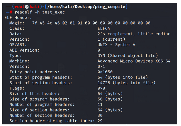
Figure 1 - Metadata Content for an ELF Executable File.
In the diagram, we can observe, among others:
Magic bytes - These are bytes at the beginning of the ELF file, serving as a unique identifier. They are used by the operating system to recognize and differentiate the ELF format from other file formats.
Class - The class field specifies the target system's architecture, determining whether the ELF file is intended for a 32-bit or 64-bit system. Two common values for this field are:
- ELF32 (32-bit class): Indicates a 32-bit system.
- ELF64 (64-bit class): Indicates a 64-bit system.
Data - This field indicates how binary data is ordered in memory. Computers can store multi-byte data with the most significant byte (MSB) first (big-endian) or the least significant byte (LSB) first (little-endian). If you're unsure about the encoding, attempting reverse engineering could lead to incorrect addresses. In the pwntools library, when reading an ELF file, you can specify the encoding.
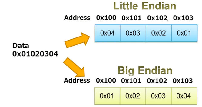
Figure 2 - Little vs Big Endian, Data stored in reverse order depending on how we want to encode it. Source: iar.com.
Entry Point Address - The initial address for program entry.
If you're interested in delving deeper into the details of the other sections of the ELF format, you can visit the following blog:
What happens when we execute a program?
The following are the sequential steps:
- Checking the "magic number"
- Checking the ELF header
- Checking the program header
- Loading segments
- Memory allocation
- Copying segments to allocated memory
- Jumping to the entry point (program start)
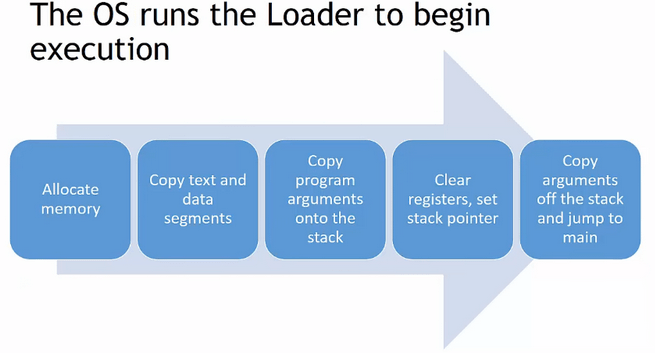
Figure 3 - Representation of program start after its execution, Source: EngMicroLectures.
At the lowest level, the processor communicates with memory, performs logical operations, and translates them into electrical impulses. If the processor needs to process data, it performs operations in registers, which are very fast memory cells located within the processor.
Ones and zeros read by the processor trigger specific operations at the electrical level, causing certain circuits to connect and perform logical operations.
All loops, conditionals (ifs), and objects are actually abstract constructs that assist humans.
Operation Codes, Assembly Language
It should be understood that the processor in our computers has access to only a limited number of mathematical/logical operations represented by operation codes -> https://en.wikipedia.org/wiki/Operation_code
Computers, as we have already mentioned, understand only machine code. So, how does assembly language relate to a sequence of these zeros and ones as shown in the image below?
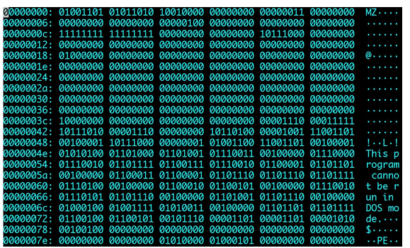
Figure 4 - Contents of a Binary File.
Well, in assembly language, the aforementioned operation codes appear. These are numbers that constitute a part of an instruction sent to the processor for execution, indicating which operation is to be performed. Each assembly command such as add, sub, etc., has its own number, which gets translated into machine code during compilation. The set of codes for a specific processor is determined by its programming model.
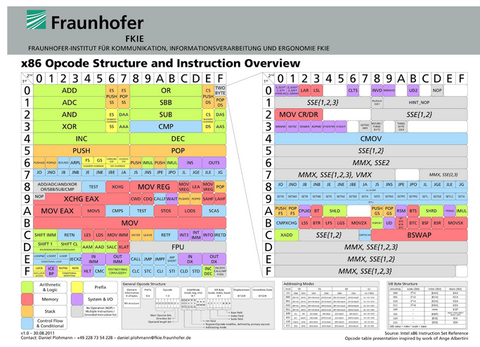
Figure 5 - Operation Codes for the x86 Architecture, Source: Fraunhofer, FKIE.
What is ISA?
The Instruction Set Architecture (ISA) is a component of the abstract computer model that defines how software controls a processor. ISA serves as the interface between hardware and software, determining both what operations the processor can perform and how to execute them.
ISA provides the only way for users to communicate with the hardware.
Processors with the same programming model are compatible, meaning they can execute the same programs and produce the same results. In the early history of processors, the processor's programming model depended on the physical implementation of the processor and often emerged entirely from it. Currently, the trend is the opposite, where various physical implementations (microarchitectures) from different manufacturers adhere to the same ISA. For example, an AMD and an Intel processor, despite having different physical designs, can have the same set of instructions – somewhat like an API independent of physical implementation.
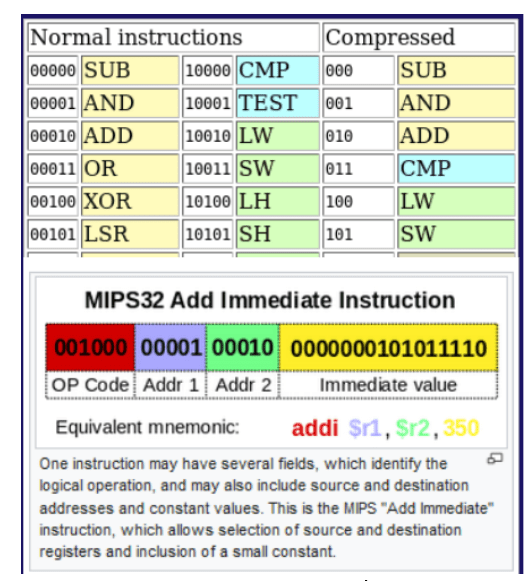
Figure 6 - Operation Codes for MIPS32, Source: Wikipedia.
In summary, there are various types of assembly languages tailored for different architectures with distinct instruction sets. An assembler program translates assembly language into machine code for a specific processor. Consequently, each CPU architecture has at least one assembler capable of converting assembly language into machine code for that processor.
This implies that:
- There are many types of assembly languages like x86, ARM, MIPS.
- Assembly language represents syntax.
- Each processor has an ISA (Instruction Set Architecture) that specifies which assembly language instructions can be used.
If you'd like to learn more on this topic, we encourage you to visit the following links:
- https://www.quora.com/What-is-the-actual-difference-between-x86-ARM-and-MIPS-architectures
- https://stackoverflow.com/questions/3527026/assembly-language-more-than-one-type
- https://www.educba.com/arm-vs-x86/
- https://en.wikipedia.org/wiki/Instruction_set_architecture#List_of_ISAs
Compilation - Continued
Let's begin by recalling the entire compilation process using this diagram.
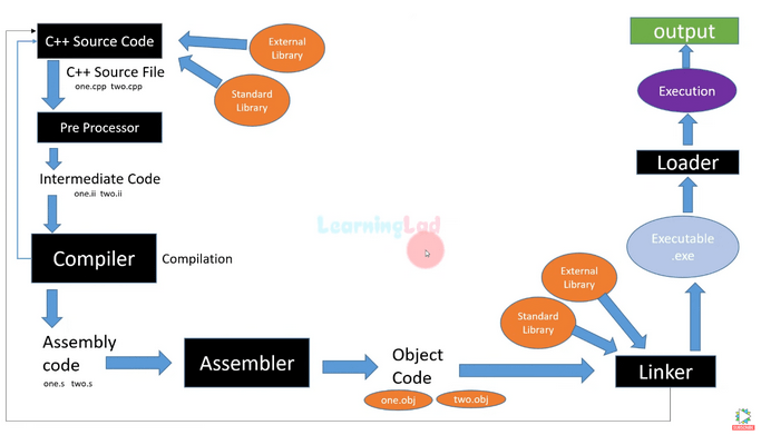
Figure 7 - Compilation process - Source: LearningLad.
Initially, the source code goes through the preprocessor, where header files are attached, and constants are resolved into values. Then, the compiler transforms the source code into assembly language code. Subsequently, the assembler (a program that compiles assembly language into binary format) generates object files (.obj, .o). Finally, the linker resolves dependencies between individual files and combines everything into a single binary file.
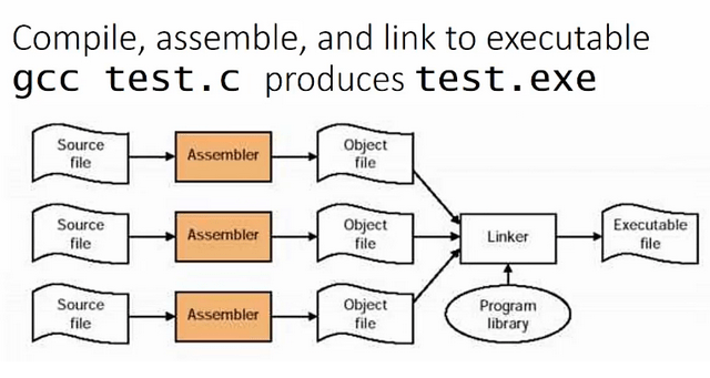
Figure 8 - Compilation of Multiple Files Simultaneously - Source: EngMicroLectures.
We can create programs consisting of multiple files and recompile only those that we modify, rather than the entire project created.
Syntactic, Lexical, and Semantic Analysis
It's also worth mentioning that the above diagrams do not fully cover the topic, as they omit both the parsing stage of source code and its optimizations. The initial stages can be described more precisely as follows:
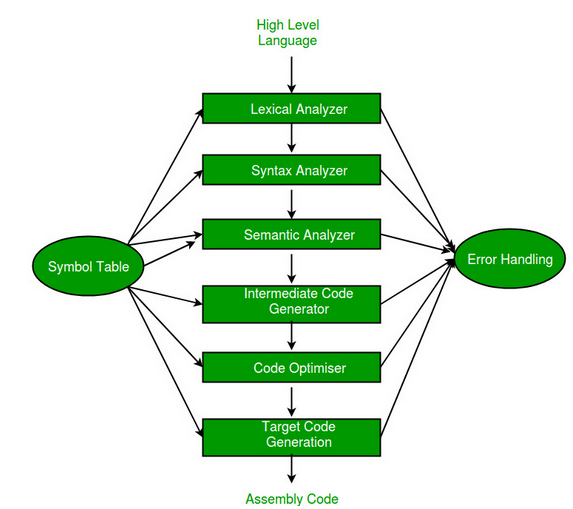
Figure 9 - Initial Stage of Compiling Source Code to Assembly.
At the start, the compiler performs lexical analysis (identifies tokens) and then removes white spaces. You can think of this simplistically as finding words in a sentence. Syntactic analysis, also known as parsing, involves analyzing a sequence of characters in a natural or programming language according to the rules of a formal grammar. Parsing data involves processing information, organizing it, and providing structured data. Semantic analysis uses syntax trees and symbol tables to check whether the code is semantically correct. It checks things like type compatibility. Following this, code optimization may occur, which makes it execute faster and with fewer assembly language instructions.
Summary
We hope that today's post has shed light on the workings of processors and the compilation process. Next week, we will discuss what an interpreter actually is and why it significantly differs from the classical approach.
Sources:
- https://www.youtube.com/watch?v=N2y6csonII4
- https://www.quora.com/What-is-the-actual-difference-between-x86-ARM-and-MIPS-architectures
- https://stackoverflow.com/questions/3527026/assembly-language-more-than-one-type
- https://www.educba.com/arm-vs-x86/
- https://en.wikipedia.org/wiki/Instruction_set_architecture#List_of_ISAs
https://www.youtube.com/watch?v=T1C9Kj_78ek - https://www.iar.com/knowledge/learn/programming/migration-techniques-for-different-endianness/
- http://ref.x86asm.net/coder32.html#x00
- https://youtu.be/nC1U1LJQL8o
- https://www.youtube.com/watch?v=N2y6csonII4